
Novel lightweight antenna arrays can reduce satellite launch costs
Launching a satellite is expensive — costing tens of millions of dollars — and researchers are constantly searching for ways to reduce the cost. Weight is a significant contributing factor to launch cost because more weight requires more lifting power, which necessitates a bigger, more expensive rocket. And utilizing expensive rockets lessens the opportunities to send experiments and key instruments, such as weather satellites, into space. One solution to lower the cost is to lower the overall weight of the satellite by building lighter components, but doing so without compromising function is a challenge. At MIT Lincoln Laboratory, a team of researchers has taken on part of this challenge by developing an antenna array panel that is lighter and more compact than existing technologies.
"If the density of the design is lower, then the launch cost will be lower because the total payload weight will be lower," said Pierre Dufilie, a researcher in the Laboratory's RF Technology Group. "And if the volume per unit area is lower, then you can fit a larger array on the same payload."
The team's lightweight array is an active electronically steered antenna (AESA), which is used for satellite communication links and remote sensing. An AESA is favored in space-based missions because operators can use them to steer and point radio wave beams in different directions without moving the antenna itself.
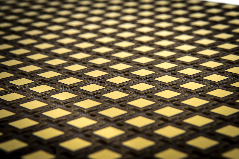
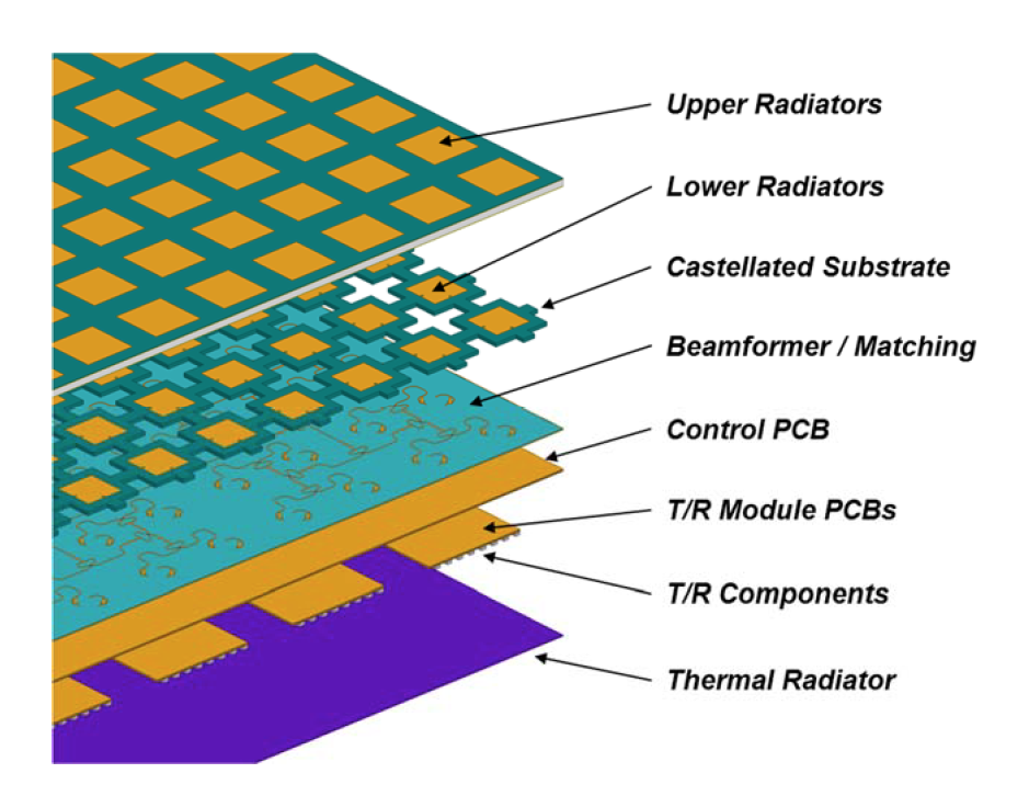
To build their array, the Laboratory team developed a new weight-reduction technique for creating a stacked microstrip antenna. For this technique, material in the antenna's radiator layer — which is made mostly of foam with printed circuit boards arranged on top — is cut away at the manufacturing stage. The cutouts are cross-shaped, and they reduce the mass of the antenna by 35 percent.
"The cutouts were placed in between the radiating elements such that the maximum amount of material is removed from the lower printed circuit board without significantly affecting the active input match for the antenna array over the full range of scanning," Dufilie said. "Simulations verified that the active input impedance match would not be significantly affected from the cutouts. Removing this printed circuit board material in the areas of the cutouts leaves voids in the board, which do not contribute to the total weight."
In the end, this technique creates an array that is five times more compact and six times less dense than current panel designs.
The research team tested the new array via computer simulation using full-wave 3D electromagnetics software and also built a prototype panel. Their results showed that the cross-shaped holes in the array caused no significant effect on the radio frequency performance.
Dufilie explained that designing and creating this new array was like looking at a complicated puzzle: "When you design something for space, you're limited in materials and approaches, and you have a very strict power budget," because only a limited amount of weight on a spacecraft can be used for batteries. "You have all those different concerns, so you have to look at it from all those different angles."
Now, the team is looking for ways to further reduce the array's weight and partnerships to further test the panels to prepare them for space-based applications.
This research is sponsored by the Under Secretary of Defense for Research and Engineering and is administered through the Laboratory's Technology Office.